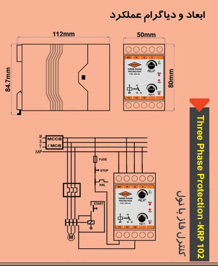
Recognition of changes in phase sequence Recognition of a phase loss Recognition of asymmetry in voltage of three phases Recognition of network undervoltage Having display signals of input supply, normal status (output energization), phase sequence, asymmetry in voltage of three phases, undervoltage
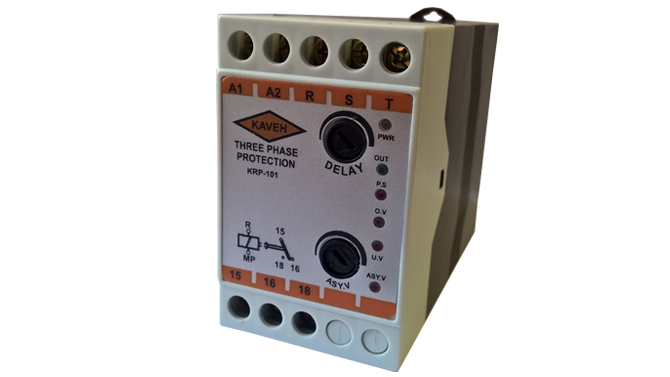
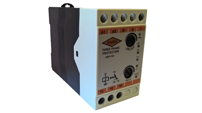
Principles of Operation: The device starts working after connection of three phases to terminals R, S, T and null to mp terminals .
In the absence of an error in the circuit, the output signal turns green
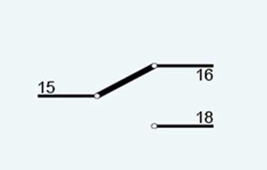
. At the end of adjusted time by DELAY potentiometer handle, OUT signal gets ON and the device internal relay opens (internal contact of terminal 15 to 18 is made).Attention: Timing does not start where any fault signal is on.
In the case of any fault like undervoltage, a phase loss or phases reversal in network, the related fault signal gets ON, OUT signal gets OFF and internal relay closes simultaneously (internal contact of terminal 15 to 16 is made).
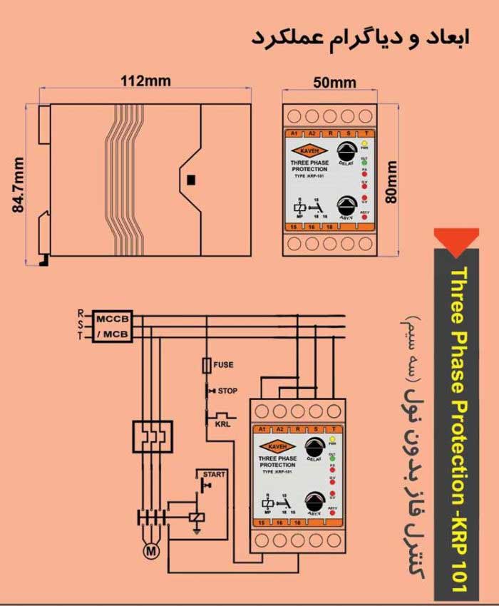
Installation and Start-Up: The network three phases have to be connected to terminals R, S, T and null to mp terminal.
Terminals 15 and 18 have to be in series in circuit like a stop button.
If sequence signal is on after device installation, the location of two phases on Three-Phase-Monitor should be reversed (e.g. R, S) for related signal to be off. Once any of the mentioned faults happen, internal relay closes and relay opens at the end of time [adjusted by DELAY potentiometer handle] and OUT signal gets ON right after fault correction. This time ranges from 0.5 to 30 seconds.
Recognition of asymmetry in voltage of three phases gets adjusted by ASY.V potentiometer handle. This value could be set in range of 5 to 15%.
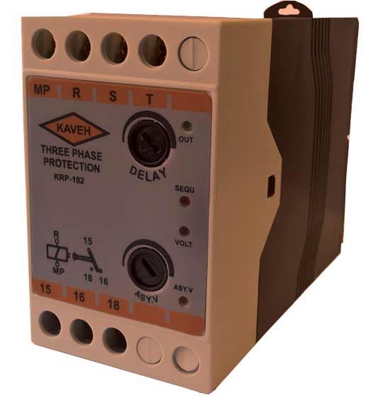
Device Signals:
OUT: Output relay energization
SEQU: Phase sequence
VOLT: Network voltage under 20% (about 300 V)
ASY.V: Phase loss or asymmetry in network voltage (over the limit adjusted by ASY.V potentiometer handle)
Technical Specifications: Supply Voltage: 380 VAC with (– 20 , +10 % )
Network Frequency: 50 or 60 Hz
Internal Loss: 3 W
ON Delay: 0.5 to 30 seconds- adjustable by DELAY potentiometer handle
Network Voltage Symmetry: 5 to 15%- adjustable by ASY.V potentiometer handle
Environmental conditions: -20 to +60 ° C with a humidity of 90%
Output relay: Single-C/O contact
 Degree of protection: IP20 Contact Current:
 7 A, 220 VAC
10 A, 28 VDC
Mounting:
In all the directions
All other technical specifications available upon request
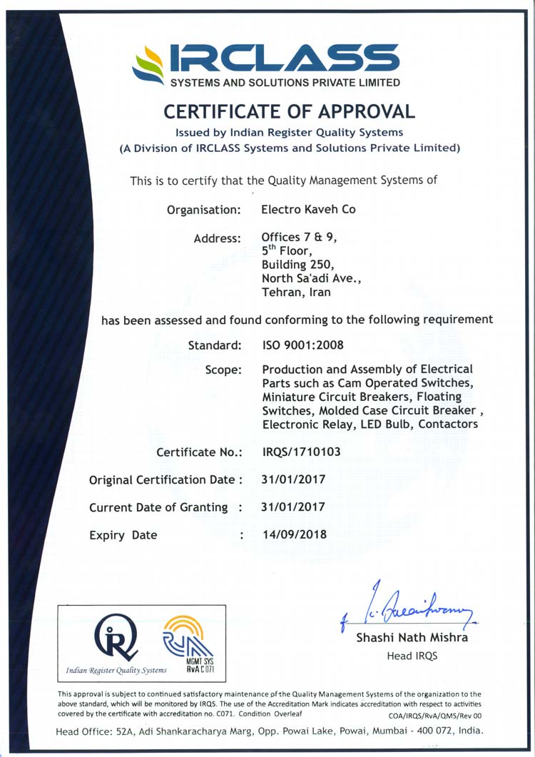
Certificate: ISO 9001 : 2008
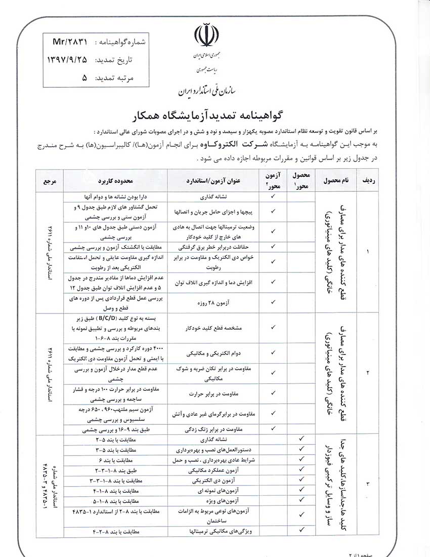
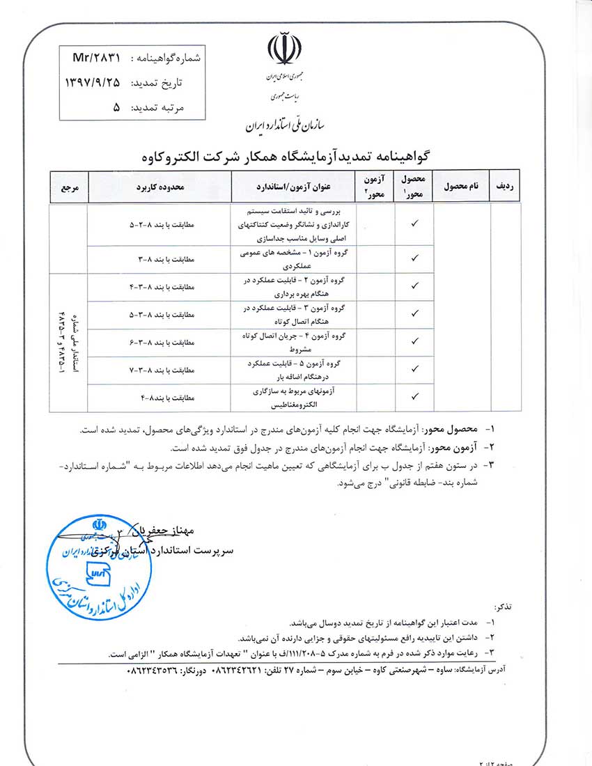
Standards: IEC/EN 60255-22 IEC/EN 60255-25 IEC/EN 60255-27 ISIR 4221-1 ISIR 4221-21